Most of the current FPGA development is done in the pattern of "Synchronous circuit + Combinational circuit".
With the increase in speed and scale of FPGAs, the clock path in synchronous circuits has become longer, causing more timing errors and other problems.
Since the clock is the same for each step of the pipeline, it is necessary to adjust the frequency to the part of the pipeline with the longest processing time.
If the processing time for each step is significantly different, adjustments such as separating the steps will be necessary.
There is no clock equivalent in the human brain, which is currently the most sophisticated and flexible information system.
Information is processed between nerve cells by passing pulsed electrical signals and neurotransmitters.
Neurons transmit pulses, but there are no positive or negative pulses.
Computer-wise, only "1" is being sent intermittently.
And the frequency of the pulse transmission and the strength of the cell-to-cell coupling change the importance of the information.
In addition, there are some connections that cause excitation in the receiving nerve cell depending on the pulse between the two cells, and others that inhibit the excitation.
In digital electronic circuits, processing is usually done bit by bit.
A single bit can only take on two states, 1 and 0.
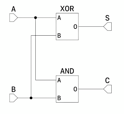
The half adder of the combinational circuit looks like this
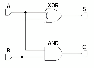
The information comes in from the A and B terminals, and the calculation results are output to the S and C terminals.
There is a problem with this circuit.
Since a bit can only represent two states, 1 and 0, it cannot represent whether the information exists or not.
Therefore, this circuit cannot know when the operation is finished.
The solution is not to use bits as the smallest unit of information, but to use something that can represent the three states of "no information", "0", and "1".
This corresponds to the presence or absence of a pulse and the coupling of excitation and inhibition in the human brain, as mentioned earlier.
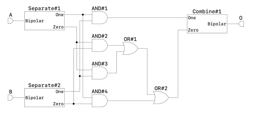
Since it is difficult to represent three types in an electronic circuit, we will use three of the four types as a set with two bits.
In SchemaHD, a set of information can be easily defined as an interface.
We defined it as a Bipolar type.
| Name |
ID in ZIP file |
ID in embedded parts |
| Bipolar BUFFER | c95mr42mjfmhsy69zdr65d7nx9 | abtsf0jqfat9yzwt2wc8q4caw1 |
| Bipolar NOT | jkakt8h1tc9rycemtx196v2hxa | abvbmbv1aqxttfacy8xmmwpaxa |
| Bipolar AND | d6zv12ggrh4bc93c9b1wk886hy | abvk9y3qd2gxdcestbwjdb8a7w |
| Bipolar NAND | p6rdjejkjrmce8kh45kx11shd7 | abvx9zswhvmpm8hdakgw8y6gg8 |
| Bipolar OR | dyerbt36wrbg61xeafqz3cgpxe | abwb3vxcybt0vtv2cet3rrhzd5 |
| Bipolar NOR | yy9pxwhpt5x933198jtdxa2z3y | abwvxacdfz3v1fnph1xk3jk4wr |
| Bipolar XOR | jj1gcy8szkeyzntnvvqtg110qs | abx5arahvcdr6yxww7v1rdg1bv |
| Bipolar XNOR | gb0fsxtk7pag26h3f4n5y6rc3z | abxk1dpk5kqfjhjq6rq0kky1hb |
| Bipolar Void | vfxd7ck3r2qxq9486gyyscddwx | abxws3wprgh7pxmwrmd5hcjbwc |
| Bipolar One | vbf1enxgpj2arebr3ymcbaqb7n | abyb3wr5gae5mfh2xzw3m4y0q0 |
| Bipolar Zero | rcnw58mp1bbyp0vsb7v7539tph | abymt7xhenhf1jr9rjjsbcjdk0 |
| Bipolar Merge | w9jmqqknk60se93jsqztp0m7d4 | abyz3w4fsgnadq5fgkrd3j7gr4 |
| Bipolar Mux | cx1ax50gn020fvvambnyx8h2x8 | abzjqnc0vvjq1w8zn6x7m2n7e3 |
| Bipolar DeMux | n26ez8wzt85rbs8jk33gbent95 | abztxzfksxk9cfp6zd1m1g4d1m |
| Bipolar Valid | b3z4q9zdh4hw81094q9by0stx6 | abzzkmdg4sdy9bagqxzhvfd5jt |
| Bipolar Waiting | tjrnrap92xacy50dqhrvg0fm93 | ac0tes8yxyd6y5q8gkmt0vmy1d |
| Bipolar Latch | r3hdga783gkmmyn0r0krj0xajk | ac1gpn0wneaejnnr4dv3b6dspm |
| Bipolar Combine | y5azamqzqjaj1smk7dzbbdp3mt | ac1wr9yhnz3mhnvsmkqgf6emah |
| Bipolar Separate | kwmxgtsc9a6h6nv76qkxx535bk | ac2vvfnw5n3pfrtpg7a4gsvx1j |
| Bipolar Half Adder | jts4tz58y7mbap3bwkn6bt64qz | ac3gazre5pw1xj0zwx9m3gf9rr |
| Bipolar Full Adder | qpymtxha24ws9wv209s30tdkg6 | ac3tw2wtgsagbkrw9hff0hz6w9 |
 Japanese
 English